IS-IS Operation and Design – Routing Protocol Characteristics, EIGRP, and IS-IS
This section discusses IS-IS areas, designated routers, authentication, and the Network Entity Title (NET). IS-IS defines areas differently from OSPF; area boundaries are links and not routers. IS-IS has no BDRs. Because IS-IS is an OSI protocol, it uses a NET to identify each router.
IS-IS NET Addressing
Although you can configure IS-IS to route IP, the communication between routers uses OSI PDUs. The NET is the OSI address used for each router to communicate with OSI PDUs. A NET address ranges from 8 to 20 bytes in length and is hexadecimal. It consists of an authority and format identifier (AFI), area ID, system ID, and selector (SEL), as shown in Figure 3-10. The system ID must be unique within the network. An example of an IS-IS NET is 49.0001.1290.6600.1001.00, which consists of the following parts:
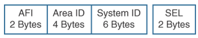
Figure 3-10 IS-IS NET
- AFI: 49
- Area ID: 0001
- System ID: 1290.6600.1001
- SEL: 00
Level 2 routers use the area ID. The system ID must be the same length for all routers in an area. For Cisco routers, it must be 6 bytes in length. Usually, a router MAC address identifies each unique router. The SEL is configured as 00. You configure the NET with the router isis command. In this example, the domain authority and format identifier (AFI) is 49, the area is 0001, the system ID is 00aa.0101.0001, and the SEL is 00:
router isis
net 49.0001.00aa.0101.0001.00
IS-IS DRs
As with OSPF, IS-IS selects DRs on multiaccess networks. It does not choose a backup DR, as OSPF does. By default, the priority value is 64. You can change the priority value to a value from 0 to 127. If you set the priority to 0, the router is not eligible to become a DR for that network. IS-IS uses the highest system ID to select the DR if there is a tie with the priorities. On point-to-point networks, the priority is 0 because no DR is elected. In IS-IS, all routers in a multiaccess network establish adjacencies with all others in the subnetwork, and IS-IS neighbors become adjacent upon the discovery of one another. Both of these characteristics are different from OSPF behavior.
IS-IS Interface Types
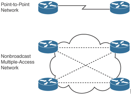
IS-IS has only two network types (or interface types): point-to-point and broadcast. Unlike OSPF, IS-IS does not have nonbroadcast and point-to-multipoint interface types.
IS-IS Area Design
IS-IS uses a two-level hierarchy. Routers are configured to route Level 1 (L1), Level 2 (L2), or both Level 1 and Level 2 (L1/L2). Level 1 routers are like OSPF internal routers in a Cisco totally stubby area. (OSPF is covered in Chapter 4.) An L2 router is similar to an OSPF backbone router. A router that has both Level 1 and 2 routes is similar to an OSPF area border router (ABR). IS-IS does not define a backbone area like OSPF’s area 0, but you can consider the IS-IS backbone a continuous path of adjacencies among Level 2 ISs. When you are creating a backbone, there should never be Level 1 routers between L2-only or L1/L2 routers.
L1/L2 routers maintain separate link-state databases for the L1 routes and for the L2 routes. Also, the L1/L2 routers do not advertise L2 routes to the L1 area. L1 routers do not have information about destinations outside the area and use L1 routes to the L1/L2 routers to reach outside destinations.
As shown in Figure 3-11, IS-IS areas are not bounded by the L1/L2 routers but by the links between L1/L2 routers and L2 backbone routers.
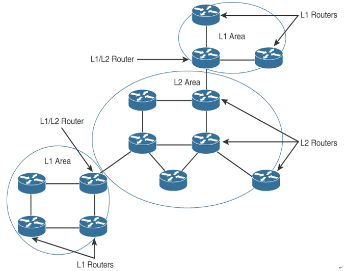
Figure 3-11 IS-IS Areas and Router Types
With IS-IS, you can create three types of topologies:
- Flat
- Hierarchical
- Hybrid
The IS-IS flat design consists of a single area. As shown in Figure 3-12, all routers are on the same level. There is no summarization with this design. This design is recommended for a small network.
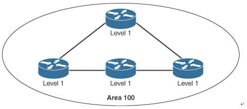
Figure 3-12 IS-IS Flat Topology Design
An IS-IS hierarchical topology is recommended for large networks. A backbone area can be created, much as with OSPF, and can have other areas connected via L1/L2 routers, as shown in Figure 3-13. This design allows for network summarization.
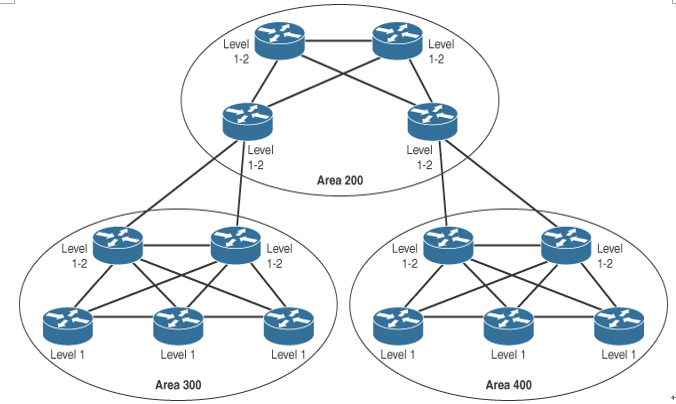
Figure 3-13 IS-IS Hierarchical Topology Design
A hybrid IS-IS design is recommended for networks that might not be large enough for a backbone area. As shown in Figure 3-14, the IS-IS areas are connected using L1/L2 routers. This design allows for summarization between areas.
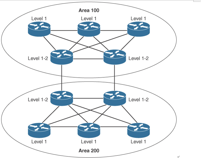
Figure 3-14 IS-IS Hybrid Topology Design